The AV-156A-B and AV-156A-C pulse constant current generators are capable of generating up to 5 Amps into
load voltage between 0 and 15 Volts. These models are popular in optoelectronic laser diode applications, as well
as the testing of airbag squibs for automotive applications.
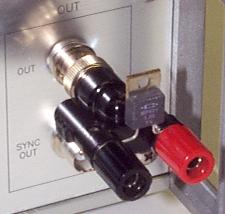
Ideally, to obtain the very best waveform possible, the load (or "device under test") should be connected as closely as possible to the output connector. The photograph below shows a 1 Ohm test load (a high-power, low-inductance, Caddock MP821-1.0-1% resistor in a TO-220 package) installed on a BNC-to-post adapter (Pomona model 1296). The adapter connects directly to the BNC "OUT" connector.
With this set-up, the following output waveform is obtained:
The top waveform is the voltage across the 1 Ohm, and the bottom waveform is the output of the AV-156A-B current monitor (which generates 0.5V per Amp, approximately). As you can see, a fast, clean rise time is obtained.
Unfortunately, it is often not possible to locate the load extremely close to the pulse generator, and so some cabling is generally required. If overshoot is not a problem in your application, standard 50 Ohm transmission line can be used to connect the load to the pulse generator.
If a 1 meter length of standard RG-58A 50 Ohm transmission line is inserted between the output connector and the load, some distortion is introduced the waveform, due to the mismatch between the 50 Ohm cable and the 1 Ohm load. This is shown below:

A 6% overshoot is seen. This overshoot becomes worse if the cable length is extended. For instance, for a 3 meter length of RG-58A cable, an 8% overshoot is observed.
If overshoot can not be tolerated, a better match must be made between the characteristic impedance of the cabling and the impedance of the load. For cable lengths up to 1 meter, Avtech can supply special low characteristic-impedance transmission lines. For instance, the waveform below shows the output when the 1 Ohm load is connected to the AV-156A-B with a 1 meter length of Avtech AV-LZ1 cable, which has 1 Ohm characteristic impedance:
The output has dramatically reduced overshoot, as compared to the 1 meter length of RG-58A cable.
For lengths beyond 1 meter, AV-LZ1 cabling is not available. However, an improved match can nonetheless be made by connecting several inexpensive 50 Ohm transmission lines in parallel. This will reduce the effective characteristic impedance of the cable bundle as a whole. For instance, for the waveform photo shown below, four 3 meter lengths of standard RG-174A 50 Ohm cable were connected in parallel, which yields an effective characteristic impedance of 12.5 Ohms (i.e., 50 Ohms / 4). This produces an excellent waveform, despite the long distances involved:
(version 1.1, August 19, 1999)
