Most Avtech high-speed pulse generators are intended for use with a 50 Ohm load. Some pulse generators are very intolerant of other load impedances. In general, the suitability of the pulse generators depends on:
- The pulse generator's rise time (tR).
- The pulse generator's output impedance (ZOUT).
Basic Rules
As a general rule, pulse generators with rise times of 2 ns or less must be used with 50 Ohm loads. They will not operate properly with non-50-Ohm loads. The datasheets for these instruments will note that the expected load is 50 Ohms. In some moderately-fast situations, these instruments can still be used with non-50-Ohm loads if series or shunt resistance is added to the load to change the overall effective load resistance to 50 Ohms. However, for the very fastest applications (tR ≤ 100 ps), a proper high-bandwidth 50 Ohm load is required.
In contrast, most pulsers with rise times in excess of 10 ns are suitable for use with loads of 50 Ohms or higher. The datasheets for these instruments will usually note that the expected load is "RL ≥ 50 Ohms". To minimize ringing, however, it may still be desirable to add series or shunt resistance to the load to change the overall effective load resistance to 50 Ohms. Alternatively, back-matching can be used to minimize ringing.
Most instruments with rise times in the range of 2-10 ns require 50 Ohm loads, either because the output circuit requires a 50 Ohm impedance to function at all, or because the reflections caused by a non-50-Ohm load would distort the signal too much. However, there is an exception to this - instruments with output impedances of 50 Ohms (ZOUT = 50 Ohms) can drive non-50-Ohms loads reasonably well, because the 50 Ohm output impedance provides built-in transmission-line "back-matching" - that is, the reflections caused by the improper load termination are absorbed by the pulse generator, rather than being re-reflected. The AVL-2-B (now discontinued) is the main example of this.
If you are unsure of the suitability of an instrument for your application, contact Avtech for clarification.
Problems with reflections, Medium Speed Pulsers (2-10ns rise time)
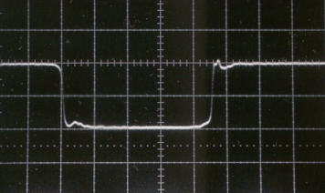
The AV-1011B1-B is a 100V pulser with 2 ns rise and fall times, and switchable output impedance. In the 100V range, the output impedance is low (near zero). In this mode, it will tolerate a moderate deviation from 50 Ohms, but since its output impedance is not 50 Ohms, reflections will occur on the output waveform because of the impedance mismatch between the 50 Ohm coaxial cabling and the non-50-Ohm load. The photos below show the AV-1011B1-B driving 40 Ohm, 50 Ohm, 100 Ohm, and 150 Ohms with a -100V pulse. These loads are connected to the AV-1011B1-B using an 18 inch (45 cm) length of RG-174 coaxial cabling.
| AV-1011B1-B, RLOAD=40 Ohms. Slight distortion, rounded waveform. 50V/div, 20ns/div |
 |
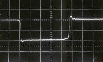
| AV-1011B1-B, RLOAD=50 Ohms. Best waveform, minimal ringing. 50V/div, 20ns/div |
 |
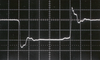
| AV-1011B1-B, RLOAD=100 Ohms. Major ringing. 50V/div, 20ns/div |
 |
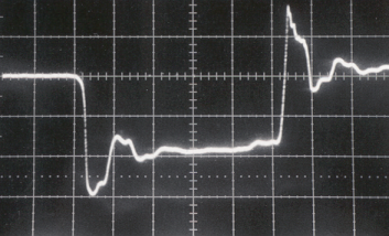
| AV-1011B1-B, RLOAD=150 Ohms. Major ringing. 50V/div, 20ns/div |
 |
Effect of Mismatched Loads on High Speed Pulsers (<2ns rise time)
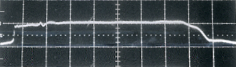
The AVR-E3-B is a 100V pulser with 0.5 ns rise time and 1 ns fall time. The photos below show the AVR-E3-B driving 36 Ohm, 50 Ohm, 83 Ohm, and 115 Ohms with a +100V pulse. These loads are connected to the AVR-E3-B using a 6 inch (15 cm) length of RG-174 coaxial cabling. The non-50-Ohm loads cause the pulser to operate improperly under some conditions (e.g., the fall time increases dramatically for RL = 36 Ohms, and the pulse width increases for RL > 50 Ohms), and reflections appear.
| AVR-E3-B. 100V/div, 5ns/div. RLOAD=36 Ohms. Severely degraded fall time. |
 |
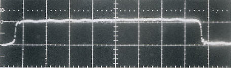
| AVR-E3-B. 100V/div, 5ns/div. RLOAD=50 Ohms. Best waveform, good rise/fall times. |
 |
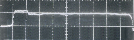
| AVR-E3-B. 100V/div, 5ns/div. RLOAD=83 Ohms. Reflections, fall time rounding, extended pulse width. |
 |
| AVR-E3-B. 100V/div, 5ns/div. RLOAD=115 Ohms. Reflections, fall time rounding, extended pulse width. |
 |
As the results show, the AVR-E3-B is only suitable for use with 50 Ohm loads.
Pulsers with 50 Ohm Output Impedance
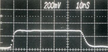
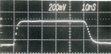
As note above, the AVL-2-B (now discontinued) pulser has ZOUT = 50 Ohms, which allows these pulsers to absorb reflections. (The AV-1011B1-B also has 50 Ohm output impedance in its 50V amplitude range.) The photos below show the AVL-2-B-P driving 36 Ohm, 50 Ohm, 83 Ohm, and 143 Ohms with the amplitude nominally set to +320V. (The actual output amplitude increases for loads greater than 50 Ohms, due to the effect of the non-zero output impedance.) These loads are connected to the AVL-2-B-P using a 12 inch (30 cm) length of RG-174 coaxial cabling.
| AVL-2-B-P, RLOAD=36 Ohms. Clean pulse, reduved amplitude. 200V/div, 10ns/div |
 |
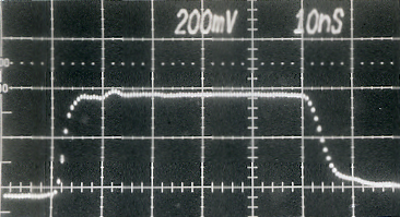
| AVL-2-B-P, RLOAD=50 Ohms. Best waveform, minimal ringing. 200V/div, 10ns/div |
 |
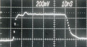
| AVL-2-B-P, RLOAD=83 Ohms. Increased amplitude, minor ringing. 200V/div, 10ns/div |
 |
| AVL-2-B-P, RLOAD=143 Ohms. Increased amplitude, minor ringing. 200V/div, 10ns/div |
 |
Simple Compensation Techniques
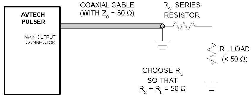
As seen above for the AV-1011B1-B, the ringing can become very large for non-50-Ohm loads. Fortunately, if the load impedance is well characterized, the user can add series or shunt resistance to change the total effective resistance of a non-50-Ohm load to 50 Ohms. For instance, if the load impedance is less than 50 Ohms, add a series resistance to boost the total resistance to 50 Ohms, as shown in the diagram:
If the load impedance is more than 50 Ohms, add a shunt resistance (i.e., in parallel):
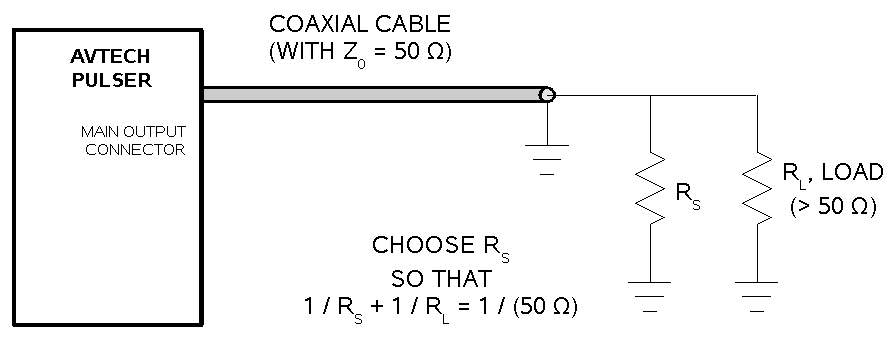
Excellent results can be obtained by adding series or shunt resistance, as appropriate. Note, however, that the RS resistor must be located very close to the load resistance (RL), or new impedance mismatches will be introduced.
These techniques are not suitable for the very fastest pulse generators (i.e., tR ≤ 100 ps, because it is very difficult to add the series or shunt resistance in a manner that does not degrade the performance of the circuits at these time scales. That is, the parasitic elements introduced by the extra circuit elements become significant at these bandwidths.
For more information about transmission lines and impedance matching, see Chapter 4 of "High-Speed Digital Design: A Handbook of Black Magic".
Backmatching Techniques (tR ≥ 10 ns)
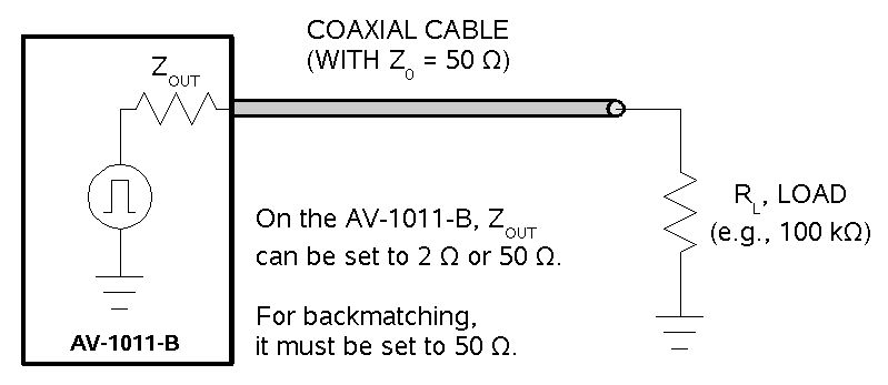
Model AV-1010-B is an example of an instrument whose output impedance can be set to 50 Ohms, for back-matching purposes. Other pulsers can typically be converted to 50 Ohm output impedance by adding a series 50 Ohm resistance at the pulse generator output.
When the pulser has been configured to operate with 50 Ohm output impedance, reflections from a mismatched load will be absorbed by the output impedance. This is useful when driving high impedance loads, as shown below:
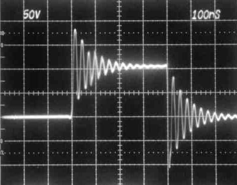
| AV-1010-B. 50V/div, 100ns/div. ZOUT=2 Ohms, RLOAD=100 kilohms, 24 inches of coaxial cabling. Severe ringing. |
 |
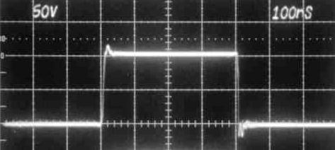
| AV-1010-B. 50V/div, 100ns/div. ZOUT=50 Ohms, RLOAD=100 kilohms, 24 inches of coaxial cabling. Minimal ringing. |
 |

