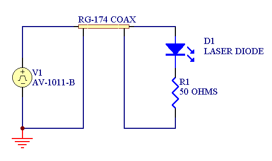
The AV-1010-B is a voltage pulse generator capable of generating ±100V into 50 Ohm loads, with less than 10 ns rise time. If a laser diode is inserted in series with the 50 Ohm resistance, the instrument acts as a ±2A current source with 50 Ohm output impedance. This method of pulsing a diode has the advantage that the 50 Ohm resistor can act as a termination for a 50 Ohm transmission line. This is illustrated in Figure 1. By using transmission line techniques, the diode under test can be located several feet away from the instrument, without incurring the large inductive voltage spikes that would normally be present.
This technique works well when driving packaged diodes, because the diode and the terminating resistance can be made into a relatively compact circuit, without adding too much series inductance. However, some end-users need to test unpackaged diodes in probing stations. Getting fast current pulses into the probing station can be a challenge, because relatively long lengths of cable, and several inches of probing needles, are present. However, since most probing stations have provision for feeding in 50 Ohm coaxial transmission lines, the technique described above can be used with a good degree of success.
Example Waveforms
To demonstrate this technique, we'll first show the pulser operation at +100V into a 50 Ohm load, connected via a 2 foot length of RG-174 coaxial transmission line, without a diode (or probing station) present. The circuit diagram is shown below:
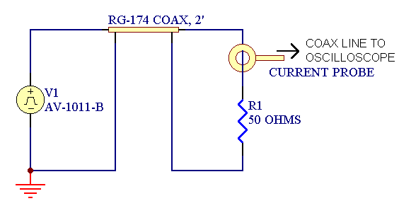
An Integrated Sensor Technologies Model 711 current transformer probe is shown in the circuit, so that the current can be measured directly. The current probe provides an output of 1 Volt per Amp. The resulting waveforms for a 100 ns wide pulse are shown below:
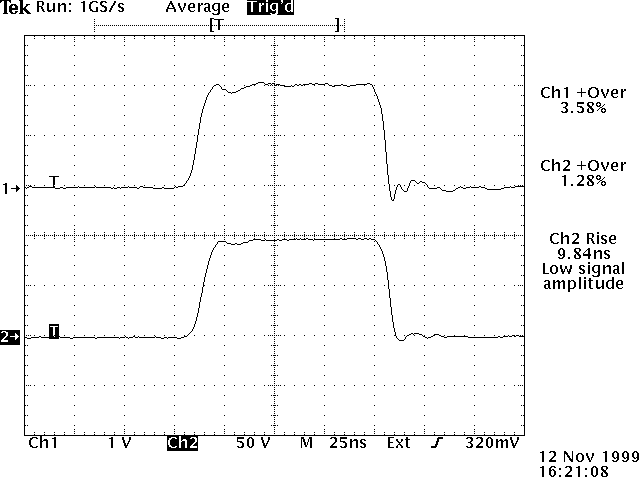
The bottom trace is the voltage across the 50 Ohm resistor, and the top trace is the output of the current transformer. The current transformer introduces a small amount of overshoot into the waveform. This photo tells us that the best current waveform that we can achieve, with an ideal termination, has perturbations on the order of 3% (this includes the current transformer's contribution).
Next, we'll add a blue-wavelength light-emitting diode in series with the current probe and resistor, as shown in the schematic:
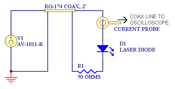
This is a less ideal termination for the transmission line, so it is not surprising when higher overshoot is observed on the output waveforms, shown below. The increased overshoot may also be partly due to the turn-on transient of the diode.
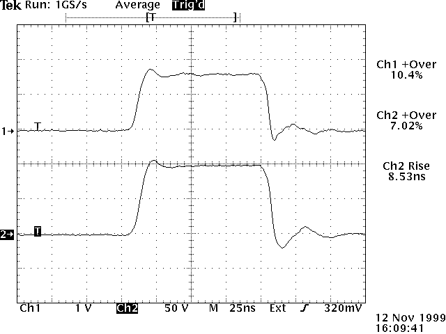
Also, due to the high forward voltage of this experimental diode (around 20V!), the output current has fallen from 2A to 1.6A (i.e., 100V-20V / 50 Ohms = 1.6 Amps).
This waveform photo establishes that the best current waveform that we can expect in a probing station will have ringing/overshoot of 10% or so.
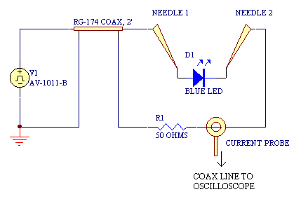
The next test establishes that we can in fact obtain this performance in the probing station. The circuit diagram shows the a 2 foot coaxial line is used to connect to the first probing needle, which contacts the diode anode. The cathode is contacted with a second needle, which in turn, is connected to the 50 Ohm terminating resistor via a 2" length of 24 AWG hookup wire. This wire is also fed through the current transformer. The 50 Ohm resistor is soldered directly to the shield of the coax input.
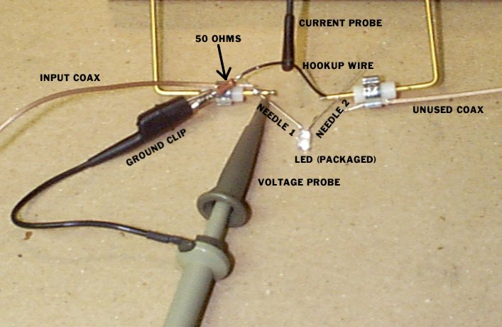
A photo of the actual test setup is shown below:
For this setup, these waveforms are obtained:

Despite the presence of the 2" of hookup wire, and approximately 2" of needle length, the waveform is as good as it was under the best-possible diode plus terminating resistance scenario illustrated previously.
Conclusion
It is possible to deliver relatively clean and fast current pulses to a device under test (DUT) in a probing station, if a voltage pulse generator is used to drive the DUT with a 50 Ohm series resistance, and if 50 Ohm coaxial cables are used.
In the example presented here, an AV-1010-B was used to deliver a 1.6 Amp pulse with rise times less than 10 ns to a blue output light emitting diode (LED).
(version 1.0, November 12, 1999)

